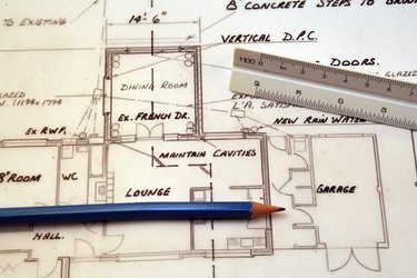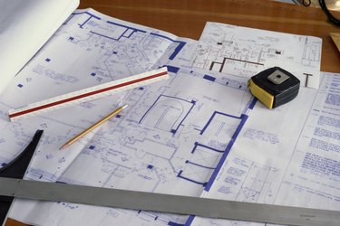
Technical drawing instruments are the tools used by professional and student drafters to render the precision graphics needed to manufacture a product or structure. These instruments take many forms because of the variety of lines and graphics needed for designs. Some instruments are manual, while others are computer-based. All professional-quality drafting instruments are manufactured with precision because the drawings they're used to make must be precise.
The following information assumes a right-handed drafter. Wherever "left" or "right" is written, the opposite direction may be substituted to apply to a left-handed drafter.
Video of the Day
Video of the Day
T-squares

T-squares are used to draw straight lines. The head of the square, the cross member, is placed along the left edge or the top of the drafting table, while the square's blade is laid across the table's top, over the drawing paper. The drafter slides the square up, down or across on the tabletop, as required by a design, always keeping the flat side of the square flush with the tabletop's edge. This action keeps the square's blade parallel to the tabletop's edges. The drafter draws a horizontal line by resting the pencil's tip atop the square's blade, then pulling the pen right while maintaining a slight pressure against the blade.
French Curves

French curves are templates used to draw smooth curves. Before using this instrument, a drafter will produce, using other instruments such as a compass, a series of points that are to form a curve, such as a circle or portion of a circle. She'll use the French curve to connect these points with a smoothly flowing curve. To do this, she'll lay the instrument on the paper next to the points to be connected. She'll then attempt to pass the instrument's edge through each of the points. If the instrument doesn't initially fit the points, she'll rotate the instrument until it does. After completing this fitting process, she'll connect the points by resting her pencil tip atop the instrument, then pulling the pencil from the leftmost point to the rightmost.
CAD Software

CAD software is used for every phase of drafting, including creation of multiple orthographic, or straight, views; drafting of pictorial and perspective views; and also animated simulations of "walkthroughs" for a structure.
The following illustrates a typical scenario involving usage of CAD software. A drafter will use his CAD program's 3-D modeling tools to create a virtual structure that fleshes out the rough sketch made by an engineer or other high-level designer for a new product. The drafter will then refine the structure by applying to it or its components his program's tools for movement, rotation and scaling. Once his design is approved by the client or the high-level designer, the drafter will forward the design to the team that will make the structure indicated by the design.