Technical drawings are used to visualize just about anything that is manufactured, built or assembled. From idea to drawing to factory, mill or construction firm, a technical drawing describes shape, dimensions, materials, construction and overall look of the object being created. With a few tips and some insight about terms and meaning, anyone can visualize the final product from looking at a technical drawing.
Understanding Projections and Views
Video of the Day
Step 1
Start by looking at the Title Block on each drawing. Located in the lower right of the drawing, the Title Block contains the architect or designer's name, the drawing number, project name, part number or building address and the scale of the drawing. This will help you understand what you're looking at.
Video of the Day
Step 2
Drawings generally include the front, side and top of the object being designed. These are labeled "front view," "top view" and "side view." These drawings are drawn in either parallel or perspective projections.
Step 3
Parallel projections include orthographic drawings: flat, multi-view drawings of the subject. These consist of a front view with the top of the object drawn on the paper below the front view and a drawing of the side view placed to the side.
Step 4
The drawing of the front of the object shows dimensions of width and height. The drawing of the top shows width and depth, and the side shows height and width.
Step 5
Perspective projections are drawings in which an object is drawn using one-, two- or three-point perspective. These drawings present the subject as a three-dimensional object.
Step 6
Section views show the hidden features of an object so that a craftsman or builder can completely understand how the piece is shaped inside and out.
Step 7
Exploded views show the pieces that make up a given object outside of the object. Connector lines indicate where the pieces go and how the unit is assembled.
Projection and Dimension Lines
Step 1
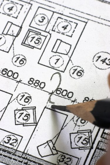
Projection and dimension lines are drawn in or around the outline of the subject and are used to indicate measurements and instructions.
Step 2
A projection line is drawn in alignment with edges of the subject or with a section such as the edges of a window or chimney. These are used to indicate the width of the indicated section.
Step 3
A dimension line is drawn from one projection line to another with arrowheads touching each projection line. Measurements are notated on dimension lines to describe what size materials should be.
Reading Symbols
Step 1
Architectural symbols are used for doors and the way they open, windows, stairs, appliances, fixtures and furniture. These symbols are generally notated.
Step 2
Other types of symbols used in architecture, landscaping and manufacturing denote the types of materials being used in the construction of a unit, part or section (i.e., marble, brick, wood, plastic, steel) and are notated.
Step 3
Electrical outlets, cables and wiring, along with duct work, are also included in a plan. Oftentimes a separate drawing (such as detailed electrical drawings) can be on lighter paper that is overlaid on the main drawing. Some notation might be included in other views of the subject.