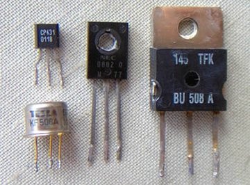
Transistors are semiconductor devices with at least three terminals. A small current or voltage through one terminal is used to control the current flow through the others. They therefore may be considered to behave like valves. Their most important uses are as switches and amplifiers. Transistors come in several types. Bipolar ones have either npn or pnp layers, with a lead attached to each one. The leads are the base, emitter and collector. The base is used to control the current flow through the other two. The emitter emits free electrons into the base, and the collector collects free electrons from the base. An npn transistor has the base as the middle p layer, and the emitter and collector as the two n layers sandwiching the base. Transistors are modeled as back-to-back diodes. For an npn, the base-emitter behaves as a forward-biased diode and the base-collector behaves as a reverse-biased diode. One widely used transistor circuit is known as a CE or common emitter connection, where the ground side of the power source is connected to the emitter.
- One 2N3904 npn transistor
- 100k resistor
- 1k resistor
- Breadboard
- Circuit wire
- Multimeter
- 3 V and 9 V batteries
You may wish to measure the voltage of both battery sources to make sure they are near the recommended values of 3 V and 9 V.
Remember the resistors may be off as much as 20 percent from the theoretical value.
Transistors are delicate components. Do not pull the leads too far apart when placing one into the circuit board.
Do not exceed the recommended maximum current or voltage into the leads.
Never wire the transistor backward.
Always exercise caution when building electrical circuits to avoid burning yourself or damaging your equipment.
Measure the resistance between the collector and the emitter. Do this by placing the multimeter on the resistance setting and by placing a probe on the appropriate terminal. If you are not sure which lead is the collector and which one is the emitter, refer to the package the transistor came in or the specifications on the manufacturer's website. Reverse the probes and measure the resistance again. It should read in the megaohm range for either direction. If not, the transistor is damaged.
Measure the forward and reverse resistances of the base-emitter leads. Do this by placing the red probe on the base and the black probe on the emitter and then reversing. Calculate the reverse to forward ratio. If this is not more than 1000:1, the transistor is damaged.
Repeat Step 2 for the forward and reverse resistances of the collector-base leads.
Wire a CE circuit. Use a base voltage of 3 V that is connected to a 100k resistor. Place the 1k resistor at the collector and connect the other end of it to the 9-volt battery. The emitter should go to ground.
Measure "Vce," the voltage between the collector and the emitter.
Measure "Vbe," the voltage between the emitter and the base. Ideally, this should be around 0.7 V.
Calculate Vce. Vce = Vc -- Ve Since this is a common emitter connection circuit, Ve = 0, and thus Vce should approximate the value of the second battery. How does the calculation compare to the measurement value in Step 5?
Calculate "Vr," the base voltage across the resistor. The base voltage source Vbb = 3 V, which is the battery. Vbe ranges from 0.6 to 0.7 V for a silicon transistor. Assume Vbe = Vb = 0.7 V. Using Kirchhoff's Law for the left-hand base loop, Vr = Vbb -- Vbe = 3 V -- 0.7 V = 2.3 V.
Calculate "Ib," the current through the base resistor. Use Ohm's Law V = IR. The equation is Ib = Vbb -- Vbe/ Rb = 2.3 V/ 100k ohms = 23 uA (microamps).
Calculate the collector current Ic. To do this, use the dc beta gain Bbc. Bbc is a current gain since a small signal at the base creates a larger current at the collector. Assume Bbc = 200. Using Ic = Bbc*Ib = 200 * 23 uA, the answer is 4.6 mA.
Things You'll Need
Tips
Warnings
Tips
- You may wish to measure the voltage of both battery sources to make sure they are near the recommended values of 3 V and 9 V. Remember the resistors may be off as much as 20 percent from the theoretical value.
Warnings
- Transistors are delicate components. Do not pull the leads too far apart when placing one into the circuit board. Do not exceed the recommended maximum current or voltage into the leads. Never wire the transistor backward. Always exercise caution when building electrical circuits to avoid burning yourself or damaging your equipment.
About the Author
Kim Lewis is a professional programmer and web developer. She has been a technical writer for more than 10 years and has written articles for businesses and the federal government. Lewis holds a Bachelor of Science, and occasionally teaches classes on how to program for the Internet.
Photo Credits
F. Dominec