Things You'll Need
- Troubleshooting and maintenance manual
- Schematic diagram of circuit to be tested
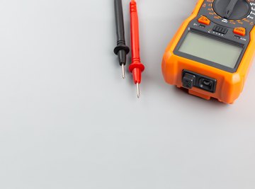
Gardner Bender digital multimeters provide an economical method of testing voltage, current, resistance and continuity in electronic devices and circuits. All Gardner Bender multimeters provide connection jacks for measuring current in amperes and floating-point decimal LCD readouts. They are battery powered for portability. A Gardner Bender multimeter is used most effectively if the voltage, current or resistance of the circuit or component is known before testing. This information is provided by the device troubleshooting manual or schematic diagram.
Always rotate the selector dial so the white indicator tip of the dial is pointing to "OFF" when not using your Gardner Bender multimeter to get the most life out of your battery.
Never attempt to measure AC voltage with the multimeter set to any range within the DC voltage measurement section. AC voltage, such as that which comes out of a standard home wall outlet, can damage the DC measurement circuitry within the multimeter. Never measure AC voltage with the dial set to any section other than the AC voltage measurement section.
Analyze the circuit diagram or schematic diagram for the circuit or component to be tested. Information you will need to know about the component or test point in the circuit includes: how many volts, how many ohms of resistance, how much current in amperes.
Plug the connector end of the black test probe wire into the bottom jack on the front panel labeled "COM", which is negative, or ground. If measuring any type of voltage (DC or AC) or resistance, plug the connector of the red test probe into the jack labeled "V (omega) mA." If measuring amperage, plug the red probe connector into the jack labeled "10A".
Test voltage with a Gardner Bender multimeter by selecting which type of voltage is to be measured. On Gardner Bender multimeters, the voltage range selection dividers on the front panel of the multimeter are located to the left and to the right of the "OFF" position. Direct current voltage selections are made in the left section and alternating current voltage selections are made in the right section. If you know the voltage to be tested should be between 20 and 200 volts, set the meter to the highest number. In this case, rotate the selector knob so the white indicator on the dial is pointing to 200. If you know the voltage is less than 20 volts, set the dial indicator to point to 20. Touch the sharp tip of the black test probe to one side of the component or circuit and the sharp tip of the red test probe to the other side of the component or circuit. Read the measurement on the LCD display.
Test resistance by moving the white indicator tip of the dial to point toward the lower-left corner of the Gardner Bender multimeter. The section for measuring resistance has an omega symbol at the bottom of the section. If you know the resistance to be measured should be between 20 and 200 kilohms (20,000 to 200,000 ohms) then adjust so the white indicator is pointing to 200k. Always select the higher number in the measured component range for the most accurate reading possible. Touch the sharp tip of the black test probe to one side of the component or circuit, then touch the sharp tip of the red test probe to the other side of the component or circuit. Read the measurement result on the LCD display.
Measure amperage in a given circuit by rotating the dial so the white indicator is pointing to the section labeled "10A" on the face of the multimeter. On Gardner Bender multimeters, the background behind "10A" is white. Be sure to move the connector of the red test probe wire to the jack labeled "10A" before attempting to measure amperage. Touch the sharp tip of the black test probe to one side of the component or circuit, then touch the sharp tip of the red test probe to the other side of the component or circuit. Read the measurement result on the LCD display.
Rotate the dial to the small white icon on the multimeter that looks like sound waves expanding outward if you desire to test a wire to make sure it isn't broken. Some Gardner Bender models provide this additional feature, and it is known as an "audible continuity test." If the wire has a connection from one end to the other, an audible or buzzing alarm will come from a small speaker on the multimeter. If a wire is broken along its length, no sound will be heard.
Tips
Warnings
References
Tips
- Always rotate the selector dial so the white indicator tip of the dial is pointing to "OFF" when not using your Gardner Bender multimeter to get the most life out of your battery.
Warnings
- Never attempt to measure AC voltage with the multimeter set to any range within the DC voltage measurement section. AC voltage, such as that which comes out of a standard home wall outlet, can damage the DC measurement circuitry within the multimeter. Never measure AC voltage with the dial set to any section other than the AC voltage measurement section.
About the Author
Kurt Schanaman has had several editorials printed by the Star-Herald Newspaper publication in Western Nebraska. He attended Western Nebraska Community College.