When you’re learning the physics of electronics, and you’ve got a good handle on the basics – like the meaning of key terms like voltage, current and resistance, along with important equations such as Ohm’s law – learning how different circuit components work is the next step to mastering the subject.
A capacitor is one of the most important components to understand because they’re widely used throughout basically every area of electronics. From coupling and decoupling capacitors, to the capacitors that make a camera’s flash work or play a key role in the rectifiers needed for AC to DC conversions, the huge range of applications of capacitors is hard to overstate. This is why it’s important you know how to calculate capacitance and the total capacitance of different arrangements of capacitors.
What Is a Capacitor?
A capacitor is a simple electrical component composed of two or more conducting plates that are held parallel to one another and either separated by air or an insulating layer. The two plates have the ability to store electric charge when they’re connected to a power source, with one plate developing a positive charge and the other collecting a negative charge.
Essentially, a capacitor is like a small battery, producing a potential difference (i.e., a voltage) between the two plates, separated by the insulating divider called the dielectric (which can be many materials, but is often ceramic, glass, wax paper or mica), which prevents current from flowing from one plate to the other, thereby maintaining the stored charge.
For a given capacitor, if it’s connected to a battery (or other voltage source) with a voltage V, it will store an electric charge Q. This ability is more clearly defined by the “capacitance” of the capacitor.
What Is Capacitance?
With this in mind, the capacitance value is a measure of a capacitor’s ability to store energy in the form of charge. In physics and electronics, capacitance is given the symbol C, and is defined as:
Where Q is the charge stored in the plates and V is the potential difference of the voltage source connected to them. In short, capacitance is a measure of the ratio of charge to voltage, and so the units of capacitance are coulombs of charge/volts of potential difference. A capacitor with a higher capacitance stores more charge for a given amount of voltage.
The concept of capacitance is so important that physicists have given it a unique unit, named the farad (after British physicist Michael Faraday), where 1 F = 1 C/V. A little like the coulomb for charge, a farad is quite a large amount of capacitance, with most capacitor values being in the range of a picofarad (pF = 10−12 F) to a microfarad (μF = 10−6 F).
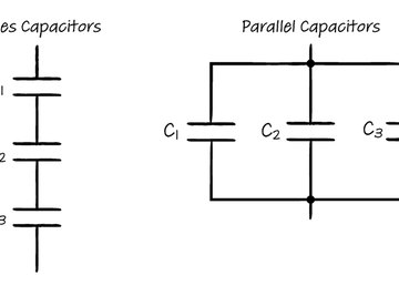
Equivalent Capacitance of Series Capacitors
In a series circuit, all of the components are arranged on the same path around the loop, and in the same way, series capacitors are connected one after another on a single path around the circuit. The total capacitance for a number of capacitors in series can be expressed as the capacitance from a single equivalent capacitor.
The formula for this can be derived from the main expression for capacitance from the previous section, re-arranged as follows:
Since Kirchhoff’s voltage law states that the sum of voltage drops around a complete loop of a circuit must be equal to the voltage from the power supply, for a number of capacitors n, the voltages must add as follows:
Where Vtot is the total voltage from the power source, and V1, V2, V3 and so on are the voltage drops across the first capacitor, second capacitor, third capacitor and so on. In combination with the previous equation, this leads to:
Where the subscripts have the same meaning as before. However, the charge on each of the capacitor plates (i.e., the Q values) come from the neighboring plate (i.e., the positive charge on one side of plate 1 must match the negative charge on the closest side of plate 2 and so on), so you can write:
The charges therefore cancel out, leaving:
Since the capacitance of the combination is equal to the equivalent capacitance of a single capacitor, this can be written:
for the any number of capacitors n.
Series Capacitors: Worked Example
To find the total capacitance (or equivalent capacitance) of a row of series capacitors, you simply apply the formula above. For three capacitors with values of 3 μF, 8 μF and 4 μF (i.e., micro-farads), you apply the formula with n = 3:
And so:
Equivalent Capacitance of Parallel Capacitors
For parallel capacitors, the analogous result is derived from Q = VC, the fact that the voltage drop across all capacitors connected in parallel (or any components in a parallel circuit) is the same, and the fact that the charge on the single equivalent capacitor will be the total charge of all of the individual capacitors in the parallel combination. The result is a simpler expression for the total capacitance or equivalent capacitance:
where again, n is the total number of capacitors.
For the same three capacitors as in the previous example, except this time connected in parallel, the calculation for the equivalent capacitance is:
Combinations of Capacitors: Problem One
Finding the equivalent capacitance for combinations of capacitors arranged in series and arranged in parallel simply involves applying these two formulas in turn. For example, imagine a combination of capacitors with two capacitors in series, with C1 = 3 × 10⁻³ F and C2 = 1 × 10⁻³ F, and another capacitor in parallel with C3 = 8 × 10⁻³ F.
First, tackle the two capacitors in series:
So:
This is the single equivalent capacitor for the series portion, so you can treat this as a single capacitor to find the total capacitance of the circuit, using the formula for parallel capacitors and the value for C3:
Combinations of Capacitors: Problem Two
For another combination of capacitors, three with a parallel connection (with values of C1 = 3 μF, C2 = 8 μF and C3 = 12 μF) and one with a series connection (with C4 = 20 μF):
The approach is basically the same as in the last example, except you handle the parallel capacitors first. So:
Now, treating these as a single capacitor and combining with C4, the total capacitance is:
So:
Note that because all of the individual capacitances were in microfarads, the whole calculation can be completed in microfarads without converting – as long as you remember when quoting your final answers!
References
- Socratic: What Are Some Examples of Capacitors Used in Circuits?
- Power Electronics: Capacitor Basics and Their Uses in Power Applications
- Electronics Notes: Capacitor Uses & Applications
- SparkFun: Capacitors
- Rapid Tables: Capacitor
- Georgia State University: HyperPhysics: Capacitors
- Peter Vis: Capacitors in Series Derivation
About the Author
Lee Johnson is a freelance writer and science enthusiast, with a passion for distilling complex concepts into simple, digestible language. He's written about science for several websites including eHow UK and WiseGeek, mainly covering physics and astronomy. He was also a science blogger for Elements Behavioral Health's blog network for five years. He studied physics at the Open University and graduated in 2018.