Electricity is the flow of electrons through a conductive material such as wire. As there are different ways for the electrons to move, there are different types of electricity. DC, or direct current, is the motion of electrons in a single direction, from one terminal of the power source to the other. AC, or alternating current, is the back-and-forth motion of electrons between the terminals of the power source, first in one direction and then the other. Different devices use different types of electricity. Some can handle large amounts of electrical current, others cannot take more than a little before burning or breaking. To address the different needs of different types of electrical equipment, engineers have created different devices to change an electric current to fit any type of device.
Transformer Function
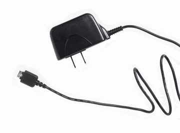
A transformer is a device that changes both the voltage and the current of an AC power source. The current remains alternating, but it has either increased or decreased in amount. When a transformer increases the current, it decreases the voltage. When it decreases the current, it increases the voltage. Because of this, the power remains constant no matter how the current changes. A transformer is often used to bring the high-voltage level of household current down to the low-voltage levels required by many small household tools and games. It is one of the two basic elements of an adapter.
How a Transformer Works
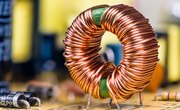
A transformer is composed of two coils of wire that do not have an electrical connection between them. One of these coils is hooked up to the power source, the other to the circuit that needs the new level of current or voltage. As the current fluctuates in the first coil, it creates a fluctuating magnetic field. This fluctuating magnetic field then induces an electrical current in the second coil. The ratio of the current in the first coil to that in the second coil is the same as the ratio between the number of turns in the second coil to the number in the first.
Rectifier Function
A rectifier is a device that turns alternating current into direct current. The current and voltage levels remain constant, as does the power, but the type of current is transformed. Many small electronic devices require DC in order to operate, but house current is always AC, as it is easier to transmit along long wires. The rectifier is the other basic element of an adapter.
How a Rectifier Works
A rectifier is made out of four diodes. Diodes are silicon devices that let current flow through them in one direction but not in the other. When they are arranged together in a diamond pattern, whichever way the AC power source tries to make the current flow, it always comes out of the diode arrangement flowing in the same direction.
References
About the Author
Jason Thompson has been self-employed as a freelance writer since 2007. He has written advertisements, book and video game reviews, technical articles and thesis papers. He started working with Mechanical Turk and then started contracting with individuals and companies directly via the Web.
Photo Credits
Ryan McVay/Photodisc/Getty Images