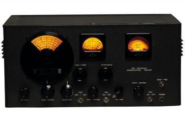
Linear amplifiers are typically preferred for use with Citizen's Band (CB) radios despite their low efficiency. This is because the CB application prioritizes low-noise over power efficiency, something which a linear amplifier offers. Weak signals can limit the operation of your CB radio and an amplifier boosts the signal. Building your own linear CB radio amplifier is advantageous because it allows greater scope for customization. It also makes future repairs easier because you know the layout, location and characteristics of each component.
Step 1
Source your parts. There are two ways to do this: Purchase the chassis, board, board-mount components, frequency meter, power supply and jacks individually or purchase all necessary components as part of a kit. The advantage of the latter is that all of the parts will be made to measure, reducing the need to drill the board. It's smart to purchase spare resistors, transistors and capacitors.
Video of the Day
Step 2
Inspect the parts. Check each part for cracks and signs of oxidization. An oxidized resistor has a brownish tint. Discard and replace any parts you suspect of being faulty. Clean the connector pins on each board-mount component with an emery board.
Step 3
Prepare the chassis. Calculate the surface area of the frequency meter, IEC power supply socket and jacks. Use a dremel tool to cut rectangular mounting-holes for the frequency meter and IEC power supply socket. The meter is located on the front panel of the chassis, the power supply socket on the rear. Use a standard electric drill and 4-mm drill bit to bore a mounting hole on each side for the jacks.
Step 4
Clean the tip of the soldering iron with a wet sponge. Dry it with a cotton cloth and turn the iron so that it is hot when you come to connect the circuit.
Step 5
Layout the circuit. Start with the resistors, then capacitors, transistors, potentiometers and relay coils. Push each into the relevant turret on the board. Use enough pressure to force the connector pins through the base of the board.
Step 6
Place the populated turret board face-down. Gently press the connector pins so that they are flat against the metal trace strip. Solder each connector pin the metal trace strip. Screw the circuit board into the base of the chassis.
Step 7
Solder a piece of power wire to the output terminal of the frequency meter, IEC power supply and jacks. The power supply has two output termini. Solder a ground wire to the output terminal of the IEC power supply.
Step 8
Mount the frequency meter, IEC power supply and jacks in the pre-drilled holes. Solder the red wire from each chassis-mount part to the circuit board. Connect the frequency to the potentiometer, the power supply to the positive eyelet on the board. Solder the ground wire to the negative eyelet on the board. Solder the input jack to the eyelet directly before the first resistor. Solder the output jack wire to the eyelet directly after the final resistor. Screw down the chassis lid.
Video of the Day