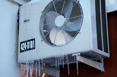
While wiring a compressor, there are a number of things to consider for a proper electrical hook up. A main concern is the amperage requirements of the compressor. This dictates the size of the wires. Another factor is if the compressor is single-phase or three-phase power. This dictates the configuration of the wiring. A home air conditioner is generally a single-phase unit, which is what this article concentrates on.
Step 1
Turn off the power and tag it, noting that the unit is being worked on. A single-phase compressor has three slide-on terminals. The terminals are normally marked, either by the terminals, or on the terminal cover. They will be marked as R, which is the run line; S, which is the start line; and C, which is the common line. In a few cases, the terminals might not be marked. The windings can be determined with the use of a multimeter.
Video of the Day
Step 2
Set your multimeter to the proper ohm setting. Check each of the terminals to each other. You will come up with three readings. Write down the readings. Between two of the terminals, there will be the highest ohm reading, This indicates that the terminals go between the start and run windings. This means that the other terminal is the common. Connect the leads of the the meter to the common terminal and to each of the other terminals. There will be two separate readings. The higher ohm reading is the start winding. The lower reading will be the run winding.
Step 3
Connect the red wire, leading to the capacitor, to the start terminal. The black wire, leading to the load side of the contactor, is connected to the run terminal. The white common line is connected in series with an overload switch that protects the compressor from overheating. The overload might be internally located in the compressor. If it is an internal overload, the white wire will be connected to the common terminal and will lead to the other side of the load side of the contactor.
Step 4
Connect the common wire to the overload switch, if it's external. It will be a small disc located directly above the terminals.
Step 5
Clamp the amp meter on the common line. Turn the power source on and check the amperage. The amps will spike momentarily while the compressor starts, but then it will read FLA (full loaded amps), listed on the data plate. If the amperage is high, shut the unit down and call a qualified service technician.
Video of the Day