A test of circuit-board components, such as capacitors, resistors, transistors and integrated circuits, can be done to some extent without removing the components from the circuit board. More comprehensive testing can be performed on these components when the component is removed. Most technicians, though, when attempting to diagnose if a circuit board component is faulty, use a volt meter to measure its input and output voltages.
Step 1
Disconnect the power from the printed circuit board and discharge all inductors and capacitors that may present a safety hazard. Confirm that the circuit board's wiring has been done correctly by examining the physical condition of each of the components on the board. Look for cracked, charred or loose components. Replace any damaged components and rewire any wiring mistakes.
Video of the Day
Step 2
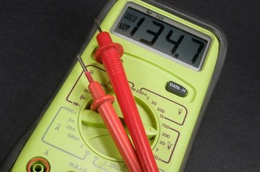
Connect and turn on the power to your circuit board again and measure the voltages on the inputs and outputs of each of the components on the board. Use your voltmeter (see Tips) to check the voltage level of all of components' input and output pins.
Step 3
Determine, for each voltage level checked, if the voltage level is the right voltage level. Rule out a component as a defective component if all the voltage level inputs and outputs are at the right voltage level.
Step 4
Turn off the power. Remove a component if all its input pins have the right voltage level but one or more of the output pins is at the wrong output voltage. Turn the power back on. Measure the voltage where the measured components pins once were. Replace a component if the voltage measurements are at the right voltage levels with the component removed.
Step 5
Measure the voltage levels of the output pins of the component (component B) that connects to the input pins of the first component (component A) checked. Do this if, and only if, component A's input pins have an incorrect voltage level. Find the wiring error if the output voltage measurements of component B's pins are not the same as the input voltage on component A's pins. .
Step 6
Repeat the procedure in Steps 3, 4 and 5 for each component and its preceding component until all of the faulty components and all of the faulty wiring have been located. Proceed in a systematic backwards fashion from the pin where the first incorrect voltage level is found, checking output pins first than input pins of each preceding component.
Video of the Day