
The alternating current (AC) in most of the appliances in your home can only come from power lines that send direct current (DC) through use of a transformer. Through all the different types of current that may flow through a circuit, it helps to have the power to control these electrical phenomena. For all their uses in changing the voltage of circuits, transformers rely heavily on their turns ratio.
Calculating Transformer Turns Ratio
A transformer turns ratio is the division of the number of turns in the primary winding by the number of turns in the secondary winding by the equation
This ratio should also equal the voltage of the primary winding divided by the voltage of the secondary winding, as given by Vp/Vs. The primary winding refers to the powered inductor, a circuit element that induces a magnetic field in response to the flow of charge, of the transformer, and the secondary one is the unpowered inductor.
These ratios hold true under the assumption that the phase angle of the primary winding equals the phase angles of the secondary by the equation ΦP = ΦS. This primary and secondary phase angle describes how the current, which alternates between forward and reverse directions in the primary and secondary windings of the transformer, are in-sync with one another.
For AC voltage sources, as used with transformers, the incoming waveform is sinusoidal, the shape a sine wave produces. The transformer turns ratio tells you how much the voltage changes through the transformer as current passes from the primary windings to the secondary windings.
Also, please note that the word "ratio" in these formula refer to a fraction, not an actual ratio. The fraction of 1/4 is different from the ratio 1:4. While 1/4 is one part out of a whole that is divided into four equal parts, the ratio 1:4 represents that, for one of something, there are four of something else. The "ratio" in the transformer turns ratio is a fraction, not a ratio, in the transformer ratio formula.
The transformer turns ratio reveals that the fractional difference that the voltage takes based on the number of coils wound around the primary and secondary parts of the transformer. A transformer with five primary wound coils and 10 secondary wound coils will cut a voltage source in half as given by 5/10 or 1/2.
Whether voltage increases or decreases as a result of these coils determines of it's a step-up transformer or step-down transformer by the transformer ratio formula. A transformer that neither increases nor decreases voltage is an "impedance transformer" that can either measure impedance, a circuit's opposition to current, or simply indicate breaks between different electrical circuits.
The Construction of a Transformer
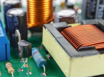
The core components of a transformer are the two coils, primary and secondary, that wrap around an iron core. The ferromagnetic core, or a core made from a permanent magnet, of a transformer also uses thin electrically insulated slices so that these surfaces can decrease resistance for the current that passes from the primary coils to the secondary coils of the transformer.
The construction of a transformer will generally be designed to lose as little energy as possible. Because not all of the magnetic flux from the primary coils pass to the secondary, there will be some loss in practice. Transformers will also lose energy due to eddy currents, localized electric current caused by changes in the magnetic field in electrical circuits.
Transformers get their name because they use this setup of a magnetizing core with windings on two separate parts of it to transform electrical energy into magnetic energy through the magnetizing of the core from the current through the primary windings.
Then, the magnetic core induces a current in the secondary windings, which converts the magnetic energy back into electrical energy. This means that transformers always operate on an incoming AC voltage source, one that switches between forward and reverse directions of current at regular intervals.
Types of Transformer Effects
Aside from the voltage or number of coils formula, you can study transformers to learn more about the nature of different types of voltages, electromagnetic induction, magnetic fields, magnetic flux and other properties that result from the construction of a transformer.
In contrast to a voltage source that sends current in one direction, an AC voltage source sent through the primary coil will create its own magnetic field. This phenomena is known as mutual inductance.
The magnetic field strength would increase to its maximum value, which is equal to the difference in magnetic flux divided by a period of time, dΦ/dt. Keep in mind, in this case, Φ is used to indicate magnetic flux, not phase angle. These magnetic field lines are drawn outward from the electromagnet. Engineers building transformers also take into account the flux linkage, which is the product of the magnetic flux Φ and the number of coils in the wire N caused by the magnetic field passing from one coil to the other.
The general equation for magnetic flux is
for a surface area which the field goes through A in m2, magnetic field B in Teslas and θ as the angle between a perpendicular vector to the area and the magnetic field. For the simple case of wrapped coils around a magnet, the flux is given by
for number of coils N, magnetic field B and over a certain area A of a surface that is parallel the magnet. However, for a transformer, the flux linkage causes the magnetic flux in the primary winding to equal that of the secondary winding.
According to Faraday's Law, you can calculate the voltage induced in the primary or secondary windings of the transformer by calculating N x dΦ/dt. This also explains why the transformer turns ratio of the voltage of one part of the transformer to the other is equal to the number of coils of one to the other.
If you were to compare the N x dΦ/dt of one part to the other, the dΦ/dt would cancel out due to both parts having the same magnetic flux. Finally, you can calculate a transformer's ampere-turns as the product of current times the number of coils as a method of measuring the magnetizing force of the coil
Transformers in Practice
Power distributions grids send electricity from power plants to buildings and houses. These power lines begin at the power plant where an electrical generator creates electrical energy from some source. This could be a hydroelectric dam that harnesses the power of water or a gas turbine that uses combustion to create mechanical energy from natural gas and converts it to electricity. This electricity is, unfortunately, produced as DC voltage which needs to be converted to AC voltage for most home appliances.
Transformers make this electricity usable by creating single-phase DC power supplies for households and buildings from the incoming oscillating AC voltage. The transformers along power distribution grids also ensure the voltage is an appropriate amount for house electronics and electricity systems. Distributions grids also uses "buses" that separate distribution into multiple directions alongside circuit breakers to keep separate distributions distinct from one another.
Engineers often account for the efficiency of transformers using the simple equation for efficiency as
for output power PO and input power PI. Based on the construction of transformer designs, these systems don't lose energy to friction or air resistance because transformers don't involve moving parts.
The magnetizing current, the amount of current necessary to magnetize the core the transformer, is generally very small compared to the current that the primary part of a transformer induces. These factors mean that transformers are typically very efficient with efficiencies of 95 percent and up for most modern designs.
If you were to apply an AC voltage source to the primary winding of a transformer, the magnetic flux that's induced in the magnetic core will continue to induce an AC voltage in the secondary winding in the same phase as the source voltage. The magnetic flux in the core, however, remains 90° behind the phase angle of the source voltage. This means the primary winding's current, the magnetizing current, also lags behind the AC voltage source.
Transformer Equation in Mutual Inductance
In addition to field, flux and voltage, transformers illustrate the electromagnetic phenomena of mutual inductance that gives more power to the primary windings of a transformer when hooked to an electrical supply.
This happens as the primary winding's reaction to an increase in load, something that consumes power, on the secondary windings. If you added a load to the secondary windings through a method such as increasing the resistance of its wires, the primary windings would respond by drawing more current from the power source to compensate for this decrease. Mutual inductance is the load you put on the secondary you can use to calculate the increase in current through the primary windings.
If you were to write a separate voltage equation for both the primary and secondary windings, you could describe this phenomena of mutual inductance. For the primary winding,
for current through the primary winding IP, primary winding load resistance R1, mutual inductance M, primary winding inductance LI, secondary winding IS and change in time Δt. The negative sign in front of the mutual inductance M shows that source current immediately experiences a drop in voltage due to the load on the secondary winding, but, in response, the primary winding raises its voltage.
This equation follows the rules of writing equations that describe how current and voltage differ among circuit elements. For a closed electrical loop, you may write the sum of the voltage across each component as equal to zero to show how voltage drops across each element in the circuit.
For the primary windings, you write this equation to account for the voltage across the primary windings themselves (IPR1) , the voltage due to the induced current of the magnetic field L1ΔIP/Δt and the voltage due to the effect of mutual inductance from the secondary windings M ΔIS/Δt.
Similarly, you may write an equation that describes the voltage drops across the secondary windings as
This equation includes the secondary winding current IS, secondary winding inductance L2 and the secondary winding load resistance R2. The resistance and inductance are labeled with a subscripts 1 or 2 instead of P or S, respectively, as resistors and inductors are often numbered, not denoted using letters. Finally, you can calculate mutual inductance from the inductors directly as
References
- Electronics Tutorials: Transformer Basics
- LiveScience: What Is Faraday’s Law of Induction?
- Schoolphysics: Flux and flux density
- All About Circuits: Mutual Inductance and Basic Operation
- Boston University: Transformers
- MagCraft: What are eddy currents?
- Clark Science Center: How Power Grids Work
- Hyperphysics: Circuit Equations:Transformer
About the Author
S. Hussain Ather is a Master's student in Science Communications the University of California, Santa Cruz. After studying physics and philosophy as an undergraduate at Indiana University-Bloomington, he worked as a scientist at the National Institutes of Health for two years. He primarily performs research in and write about neuroscience and philosophy, however, his interests span ethics, policy, and other areas relevant to science.