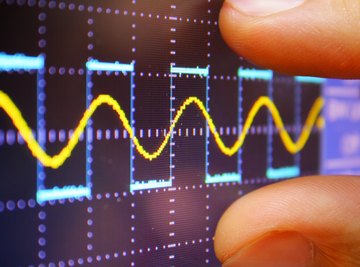
Oscilloscopes are versatile electrical measurement tools capable of displaying plots of voltage over time and over a wide range of frequencies. Oscilloscopes can be set so that the plot of a given voltage begins when a specific "trigger" condition occurs. While oscilloscopes cannot measure electrical current directly, that task requires a multi-meter, an oscilloscope can indirectly measure an electrical current. Doing so requires the use of resistors and a knowledge of Ohm's Law, but the process is not difficult.
TL;DR (Too Long; Didn't Read)
To measure electrical current through the use of an oscilloscope, attach measuring probes with resistors of known value to the electrical system or circuit you wish to measure. Be sure to use resistors with a power rating equal or greater to the system's power output if possible. You can then take a voltage measurement and with the value of the resistor, calculate the current by dividing the measured voltage by the resistance. Remember to ground yourself by wearing a grounding strap, if measuring an integrated circuit.
Oscilloscopes and Ohm's Law
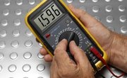
Digital Multi-Meters (DMMs) are one of the most common instruments of electrical measurement. Named for their multi-functionality, DMMs are capable of measuring current, voltage and resistance. In stark contrast, oscilloscopes are only capable of measuring the voltage of a system, which would make an oscilloscope a poor choice for measuring current if not for Ohm's Law. Ohm's Law states that you can determine the current of a resistor in amps by dividing that same resistor's voltage in volts by the resistance in ohms. In other words, if you know or can find the resistance of a system, an oscilloscope can determine current.
Preparing to Test
To begin the process of determining current, first plug in your oscilloscope. Press the AUTOSET or PRESET button on the oscilloscope if one is present. If not, set the controls to standard position. Set channel 1 to DC or AC depending on the system you seek to measure, then ensure that the trigger mode is set to auto with the trigger source as channel 1. Turn off the trigger holdoff and set the intensity control to nominal.
Testing for Voltage
Once the oscilloscope is set, ground yourself by wearing a grounding strap (if testing an integrated circuit) and attach measuring probes with resistors of known value to your electrical system. Be sure to use resistors with a power rating equal or greater to the system's power output if possible. For example, if the system's power output is 9 volts or less, use resistors rated for at least 1/8-watt. Set the oscilloscope's trigger mode to auto. Then, identify either the peak or zero voltage point to "trigger" the oscilloscope and begin measuring the electrical signal. Adjust the controls until you see a stable sine wave, then measure along the center vertical line with the smallest divisions to find the voltage of the electrical system. Take note of this measurement.
Finding Current
With the measurement of voltage in hand, calculating for current is as easy as plugging your data into the Ohm's Law formula: divide the voltage reading by the resistance of your measuring probes: the result of this calculation will be the current of your electrical system.
References
Resources
About the Author
Blake Flournoy is a writer, reporter, and researcher based out of Baltimore, MD. Working independently and alongside professors at Goucher College, they have produced and taught a number of educational programs and workshops for high school and college students in the Baltimore area, finding new ways to connect students to biology, psychology, and statistics. They have never seen Seinfeld and are deathly scared of wasps.