
An inductor is a small electronic element that resists changes in an alternating current, or AC. It consists of a series of wire loops around a core that store energy in the form of a magnetic field, related to the current that passes through it. This effect, or inductance, is dependent on the material makeup and structure of the inductor. Reactance is a measure in ohms of the relationship between the inductance and frequency of the AC.
Acquire the necessary data. You will need the inductance, measured in Henries, and the AC frequency, measured in Hertz. The inductance is usually written on the inductor itself or may be referenced in a schematic. The frequency is usually notated in an electronic schematic.
Convert inductance as needed. Inductance is frequently expressed as micro-Henries, which represents 1,000,000 Henries. To convert to Henries, you would divide the number of micro-Henries by 1,000,000.
Calculate reactance, in ohms, by using the formula: Reactance = 2 * pi * Frequency * Inductance. Pi is simply a constant, measured as 3.14.
References
About the Author
C. Taylor embarked on a professional writing career in 2009 and frequently writes about technology, science, business, finance, martial arts and the great outdoors. He writes for both online and offline publications, including the Journal of Asian Martial Arts, Samsung, Radio Shack, Motley Fool, Chron, Synonym and more. He received a Master of Science degree in wildlife biology from Clemson University and a Bachelor of Arts in biological sciences at College of Charleston. He also holds minors in statistics, physics and visual arts.
Photo Credits
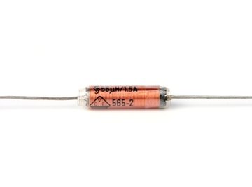
drosselspule, induction coil image by Sascha Zlatkov from Fotolia.com