Capacitors have a variety of designs for uses in computing applications and filtering electric signal in circuits. Despite the differences in the ways they're built and what they're used for, they all function through the same electrochemical principles.
When engineers build them, they take into account quantities like capacitance value, rated voltage, reverse voltage and leakage current to make sure they're ideal for their uses. When you want to store a large amount of charge in an electrical circuit, learn more about electrolytic capacitors.
Determining Capacitor Polarity
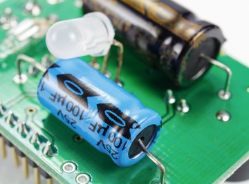
To figure out capacitor polarity the stripe on an electrolytic capacitor tells you the negative end. For axial leaded capacitors (in which the leads come out of the opposite ends of the capacitor), there may be an arrow that points to the negative end, symbolizing the flow of charge.
Make sure you know what the polarity of a capacitor is so you can attach it to an electrical circuit in the appropriate direction. Attaching in the wrong direction may cause the circuit to short circuit or overheat.
Tips
You can determine an electrolytic capacitor polarity by measuring its voltage drop and capacitance in an electric circuit. Make sure you pay close attention to the capacitor positive side and negative side such that you don't damage it or the rest of the circuit. Use safety precautions when working with capacitors.
In some cases, the positive end of the capacitor may be longer than the negative one, but you need to be careful with this criteria because many capacitors have their leads trimmed. A tantalum capacitor may sometimes have a plus (+) sign indicating the positive end.
Some electrolytic capacitors can be used in a bipolar manner that lets them reverse polarity when needed. They do this by switching between the flow of charge through an alternating current (AC) circuit.
Some electrolytic capacitors are intended for bipolar operation through unpolarized methods. These capacitors are constructed with two anode plates that are connected in reverse polarity. In successive portions of the ac cycle, one oxide functions as a blocking dielectric. It prevents reverse current from destroying the opposite electrolyte.
Electrolytic Capacitor Characteristics
An electrolytic capacitor uses an electrolyte to increase the amount of capacitance, or its ability to store charge, it can attain. They're polarized, meaning their charges line up in a distribution that lets them store charge. The electrolyte, in this case, is a liquid or gel that has a high amount of ions that makes it easily charged.
When the electrolytic capacitors are polarized, the voltage or potential on the positive terminal is greater that of the negative one, allowing charge to flow freely throughout the capacitor.
When the capacitor is polarized, it's generally marked with a minus (-) or plus (+) to indicate the negative and positive ends. Pay close attention to this because, if you plug a capacitor in a circuit the wrong way, it may short circuit, as in, a current that is so large flows through the capacitor that can permanently damage it.
Though a large capacitance lets electrolytic capacitors store larger amounts of charge, they may be subject to leakage currents and may not meet the appropriate value tolerances, the amount a capacitance is allowed to vary for practical purposes. Certain design factors may also limit the lifetime of electrolytic capacitors if the capacitors are prone to being worn down easily after repeated use.
Because of this polarity of an electrolytic capacitor, they must be forward biased. This means the positive end of the capacitor must be at a higher voltage than the negative one so that charge flows through the circuit from the positive end to negative end.
Attaching a capacitor to a circuit in the wrong direction may damage the aluminum oxide material that insulates the capacitor or short circuit itself. It can also cause overheating such that the electrolyte heats up too much or leaks.
Safety Precautions When Measuring Capacitance
Before you measure capacitance, you should be aware of safety precautions when using a capacitor. Even after you remove the power from a circuit, a capacitor is likely to remain energized. Before you touch it, confirm that all the power of the circuit is turned off by using a multimeter to confirm the power is off and you've discharged the capacitor by connecting a resistor across the capacitor's leads.
To discharge a capacitor safely, connect a 5-watt resistor across the capacitor's terminals for five seconds. Use the multimeter to confirm the power is off. Constantly check the capacitor for leaks, cracks and other signs of wear and tear.
Electrolytic Capacitor Symbol

The electrolytic capacitor symbol is the general symbol for a capacitor. Electrolytic capacitors are portrayed in circuit diagrams as shown in the figure above for European and American styles. The plus and minus signs indicate the positive and negative terminals, the anode and cathode.
Calculating Electric Capacitance
Because the capacitance is a value intrinsic to an electrolytic capacitor, you can calculate it in units of farads as C = εr ε0 A/d for the area of overlap of the two plates A in m2, εr as the dimensionless dielectric constant of the material, ε0 as the electric constant in farads/meter, and d as the separation between plates in meters.
Experimentally Measuring Capacitance
You can use a multimeter to measure the capacitance. The multimeter works by measuring current and voltage and using those two values to calculate capacitance. Set the multimeter to capacitance mode (typically indicated by a capacitance symbol).
After the capacitor has been connected to the circuit and been given enough time to charge up, disconnect it from the circuit following the safety precautions that have been just described.
Connect the leads of the capacitor to the multimeter terminals. You can use a relative mode to measure the capacitance of the test leads relative to one another. This can be handy for low capacitance values that may be more difficult to detect.
Try using various ranges of capacitance until you find a reading that's accurate based on the configuration of the electric circuit.
Applications when Measuring Capacitance
Engineers use multimeters to measure capacitance frequently for single-phase motors, equipment and machines small in size for industrial applications. Single-phase motors work by creating an alternating flux in the stator winding of the motor. This lets the current alternate in direction while flowing through the stator winding as governed by the laws and principles of electromagnetic induction.
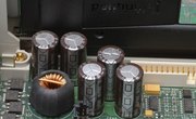
Electrolytic capacitors in particular are better for high capacitance uses such as power supply circuits and motherboards for computers.
The induced current in the motor then produces its own magnetic flux in opposition to the flux of the stator winding. Because single-phase motors may be subject to overheating and other issues, it's necessary to check their capacitance and ability to work using multimeters to measure capacitance.
Malfunctions in capacitors can limit their lifespan. Short circuited capacitors may even damage parts of it such that it may not work anymore.
Electrolytic Capacitor Construction
Engineers build aluminum electrolytic capacitors using aluminum foils and paper spacers, devices that cause fluctuations in voltage to prevent damaging vibrations, that are soaked in the electrolytic fluid. They typically cover one of the two aluminum foils with an oxide layer at the anode of the capacitor.
The oxide at this part of the capacitor causes the material to lose electrons during the process of charging and storing charge. At the cathode, the material gains electrons during the reduction process of electrolytic capacitor construction.
Then, the manufacturers continue to stack the electrolyte-soaked paper with the cathode by connecting them to one another in an electric circuit and rolling them into a cylindrical case that is connected to the circuit. Engineers generally choose to either arrange the paper in either an axial or radial direction.
The axial capacitors are made with one pin at each end of the cylinder, and the radial designs use both pins on the same side of the cylindrical case.
The plate area and electrolytic thickness determine the capacitance and allow electrolytic capacitors to be ideal candidates for applications such as audio amplifiers. Aluminum electrolytic capacitors are used in power supplies, computer motherboards and domestic equipment.
These features allow electrolytic capacitors to store much more charge than other capacitors. Double-layer capacitors, or supercapacitors, can even achieve capacitances of thousands of farads.
Aluminum Electrolytic Capacitors
Aluminum electrolytic capacitors use the solid aluminum material to create a "valve" such that a positive voltage in the electrolytic liquid lets it form an oxide layer that acts as a dielectric, an insulating material that can be polarized to prevent charges from flowing. Engineers create these capacitors with an aluminum anode. This is used to make the layers of the capacitor, and it's ideal for storing charge. Engineers use manganese dioxide to create the cathode.
These types of electrolytic capacitors can further be broken down into thin plain foil type and etched foil type. The plain foil type are the ones that have just been described while etched foil type capacitors use aluminum oxide on the anode and cathode foils that have been etched to increase surface area and permittivity, the measure of a material's ability to store charge.
This increases the capacitance, but also hinders the material's ability to tolerate high direct currents (DC), the type of current that travels in a single direction in a circuit.
Electrolytes in Aluminum Electrolytic Capacitors
The types of electrolytes used in aluminum capacitors can differ between nonsolid, solid manganese dioxide and solid polymer. Nonsolid, or liquid, electrolytes are commonly used because they're relatively cheap and suit a variety of sizes, capacitances and voltage values. They do have high amounts of loss of energy when used in circuits, though. Ethylene glycol and boric acids make up the liquid electrolytes.
Other solvents like dimethylformamide and dimethylacetamide can be dissolved in water for use, as well. These types of capacitors can also use solid electrolytes such as manganese dioxide or a solid polymer electrolyte. Manganese dioxide is also cost-effective and reliable at higher temperatures and humidity values. They have less DC leakage current and a high amount of electrical conductivity.
The electrolytes are chosen to address issues of the high dissipation factors as well as the general energy losses of electrolytic capacitors.
Niobium and Tantalum Capacitors
The tantalum capacitor is mostly used in surface-mount devices in computing applications as well as military, medical and space equipment.
The tantalum material of the anode lets them oxidize easily just like aluminum capacitor, and also lets them take advantage of the increased conductivity when tantalum powder is pressed on a conductive wire. The oxide then forms on the surface and within cavities in the material. This creates a greater surface area for an increased ability to store charge with greater permittivity than aluminum.
Niobium-based capacitors use a mass of a material around a wire conductor that uses oxidation in creating a dielectric. These dielectrics have greater permittivity than tantalum capacitors, but use more of a dielectric thickness for a given voltage rating. These capacitors have been used more frequently recently because tantalum capacitors have become more expensive.
References
- CapacitorGuide: Electrolytic Capacitor
- Design World: Basics of tantalum electrolytic capacitors
- Physics and Radio Electronics: Electrolytic capacitor
- Electronics Tutorials: Types of Capacitor
- WestFloridaComponents: Determining Polarity of Electronic Components
- Fluke: How to Measure Capacitance
- Test and Measurement Tips: How to measure electrolytic capacitors
- Sciencedirect: Aluminum Electrolytic Capacitor
Warnings
- Once you have located the polarity markings on your capacitor, be certain that you install it correctly. The capacitor will be damaged and may even explode if inserted backward into the circuit.
- Unless the capacitor is brand new, never touch both of the wire leads with your fingers, as some capacitors store a high voltage, sometimes for months, after a power source has been removed from them.
About the Author
S. Hussain Ather is a Master's student in Science Communications the University of California, Santa Cruz. After studying physics and philosophy as an undergraduate at Indiana University-Bloomington, he worked as a scientist at the National Institutes of Health for two years. He primarily performs research in and write about neuroscience and philosophy, however, his interests span ethics, policy, and other areas relevant to science.