An introduction to reading electrical schematics
- a schematic sheet for your system
- an intended purpose for reading your schematic
- references on schematic symbols
- some background in electronics or a willingness to learn
Safety! Always follow the manufacturer's safety instructions for any system.
Define your purpose for reading a schematic. For example, if you're trying to understand why the AAA batteries no longer power your DVD player's remote control after you lost the battery cover (i.e. it happened to me), that focus will keep your mind from wandering to more intricate and - for your purpose - distracting sections of the schematic. If, however, your purpose is to advance your general understanding of schematics, you may want to limit your time commitment to a few hours or whatever is consistent with your desire for learning.
Safety - If you're considering using the schematic as a guide to working on a real world system, you're entering a dangerous realm of AC power sources, stored energy (such as capacitors, chemicals/batteries), and moving parts. Such tinkering is best left to trained experts.
Limit your reading to electric signals and components. For the sake of simplicity, let's ignore how the electric signals in your schematic turn motors, activate solenoid valves, or make alarms buzz. Let's focus on tracing the signals themselves, such as power, digital logic, and analog information.
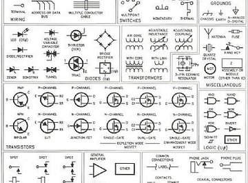
Identify the symbols in your schematic. Not all symbols are universal, and you may have to search the Internet to find the meaning of all the symbols in your schematic. I've attached an example schematic symbol reference to this article. You might be able to limit your search to those symbols relevant to your purpose. In the DVD remote example, once I find the symbol for the "on/off" button on my schematic, I can trace signal lines from that button to components that are likely to be involved with powering my remote. Note that I have professional electrical safety training and would apply such training before touching any system, even something as small as my remote.
Once you know the relevant symbols in your schematic, you can mentally identify different sections of your system. You can determine which sections or groups of components route power, accept user controls, give user indications or alarms, make things happen (i.e. turn motors, power an antenna), or involve onboard computing (i.e. integrated circuits). Knowing this is like orienting yourself on a map.
Ultimately, the truth of what's happening in any circuit is revealed in the electric signals carried in its conductors. For your schematic, this means understanding what's going on with each trace (represented by straight lines with 90 degree turns) between your system's components, (represented by the symbols). Sometimes, the traces are labeled, such as "5VDC" or "USB power", which are great clues when reading a schematic.
Once you have an idea of your purpose, a feel for what sections of your schematic do what, what relevant components your schematic symbols represent, and what traces are carrying the signals of interest to you, you have a pretty good starting point for making sense of your schematic. Depending how deeply you want to understand your schematic, you may require component-level investigation, which can be tedious. However, the good news is that many components have data sheets that explain what signals are coming into or going out of them, offering great insight to their roles within your schematic.
Things You'll Need
Warnings
Warnings
- Safety! Always follow the manufacturer's safety instructions for any system.
About the Author
This article was written by the CareerTrend team, copy edited and fact checked through a multi-point auditing system, in efforts to ensure our readers only receive the best information. To submit your questions or ideas, or to simply learn more about CareerTrend, contact us [here](http://careertrend.com/about-us).
Photo Credits
http://9w2bba.files.wordpress.com/2007/08/schematic-symbols_s.jpg