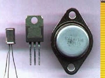
Transistors are made from semiconductors such as silicon or germanium. They are constructed with three or more terminals. They may be viewed as electronic valves because a small signal that is sent through a middle terminal controls the current flow through the others. They function primarily as switches and amplifiers. Bipolar transistors are the most popular type. They have three layers with a lead attached to each one. The middle layer is the base, and the other two are called the emitter and the collector.
Technical information on transistors may be found on their packages, on the data sheets from the manufacturer, and in some electronics textbooks or handbooks. They contain information on transistor characteristics and operation. The ones that are the most significant include the gain, dissipation and the maximum ratings.
- NPN transistor, such as a 2N3904
- Transistor data sheet or package
- Introductory electronics text
The data sheet for PNP transistors will have characteristics similar to that of NPN ones.
Find the generalized description of the transistor, which contains information on how the transistor may be used in a circuit. Its function will be described as that of amplifying, switching or both.
Observe the dissipation rating of the device. This parameter tells how much power the transistor can safely handle without being damaged. Transistors are typically described as power or small-signal, dependent on the value of this rating. Power transistors typically can dissipate a watt or more of power, while small-signal ones dissipate less than a watt. The maximum dissipation for a 2N3904 is 350 mW (milliwatts), and so it is classified as small signal.
Study the current gain parameter Hfe. It is defined as a gain because a small signal at the base produces a much larger signal at the collector. Hfe has minimum and maximum values, though both may not be listed. The 2N3904 has an Hfe minimum of 100. As an example of its usage, consider the collector current formula Icollector = Hfe_Ibase. If the base current Ibase is 2 mA , then the formula states that there is a minimum of 100_2 mA = 200 mA (milliamps) at the collector. Hfe may be also referred to as Beta(dc).
Examine the parameters for the maximum breakdown voltages. The breakdown voltage is where the transistor will stop operating or be destroyed if it is given an input voltage of that amount. It is recommended that transistors not be allowed to operate near these values, lest their lifespan be shortened. Vcb is the voltage between the collector and the base. Vceo is the voltage between the collector and the emitter with the base open, and Veb is the voltage from the emitter to the base. The Vcb breakdown voltage for the 2N3904 is listed as 60 V. The remaining values are 40 V for Vceo, and 6 V for Veb. These are amounts that should be avoided in actual operation.
Review the maximum current ratings. Ic is the maximum current the collector can handle, and for the 2N3904 this is listed as 200 mA. Observe that these ratings assume an ideal temperature that is specified or assumed as room temperature. This is usually not to exceed 25 degrees Celsius.
Summarize the data. For some 2N3904 transistors at room temperature with a collector current of less than 200 mA, and where the power rating is not exceeded, their gain will be as low as 100 or as high as 300. Most 2N3904 transistors, however, will have a gain of 200.
Things You'll Need
Tips
Tips
- The data sheet for PNP transistors will have characteristics similar to that of NPN ones.
About the Author
Kim Lewis is a professional programmer and web developer. She has been a technical writer for more than 10 years and has written articles for businesses and the federal government. Lewis holds a Bachelor of Science, and occasionally teaches classes on how to program for the Internet.
Photo Credits
Beth O'Hara/Commons.Wikimedia.org