ItStill
W
orks
Search Glass
Internet
Media
Printer
Social Media
Smart Devices
Email
Network
Hardware
Phone
Software
Page Not Found, but check out these articles below!
Types of Boring Tools
What Frequencies Are DTV?
Microsoft File Extension ICS
IEEE Standard Wiring Colors
How to Convert a Mobile Game Into a PC Game
How to Put Music on Micro SD Cards
How to Backspace on a Phone
How to Unfreeze MSN
How to Convert HDMI to RF
How to Get Rid of Double Spacing in Outlook
How to Connect My Sennheiser Bluetooth Headphones to My MacBook Pro
How to Use the Whois Command Line
How to Insert Data From a Form in PHP to a MySQL Database
How to Minimize a Photo to 100 Pixels X 100 Pixels & No More Than 6 KB
How to Protect Port 443
Logitech Speaker Installation
How to Block a Phone Number When You're Calling Long Distance
How to View SMS History for a Vodafone Number
How to Import Corel Draw CDR Files Into Visio
How To Use a Variable In a SQL String VBA
I Can't Delete Text From a PDF in Adobe Acrobat 9 Standard
The Pros & Cons of Flip Phones
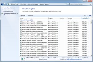
How to Remove Windows 7 Updates
Equipment Used by Water Refilling Stations
How to Block Your Phone Number From Showing
How to Burn a CD Using Windows 7
How to Copy Wireless Settings From One Laptop to Another
How to Revive a Dead Pixel
Different Ways to Copy and Paste
How to View MOV Files on Your iPhone
×