

TL;DR (Too Long; Didn't Read)
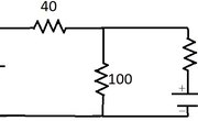
In the above parallel circuit diagram, the voltage drop can be found by summing the resistances of each resistor and determining what voltage results from the current in this configuration. These parallel circuit examples illustrate the concepts of current and voltage across different branches.
In the parallel circuit diagram, the voltage drop across a resistor in a parallel circuit is the same across all resistors in each branch of the parallel circuit. Voltage, expressed in volts, measures the electromotive force or potential difference that runs the circuit.
When you have a circuit with a known amount of current, the flow of electrical charge, you can calculate the voltage drop in parallel circuit diagrams by:
- Determine the combined resistance, or opposition to the flow of charge, of the parallel resistors. Sum them up as 1/Rtotal = 1/R1 + 1/R2 ... for each resistor. For the above parallel circuit, the total resistance can be found as:
- 1/Rtotal = 1/5 Ω + 1/6 Ω+ 1/10 Ω
- 1/Rtotal = 6/30 Ω + 5/30 Ω + 3/30 Ω
- 1/Rtotal = 14/30 Ω
- Rtotal = 30/14 Ω = 15/7 Ω
- 1/Rtotal = 1/5 Ω + 1/6 Ω+ 1/10 Ω
- Multiply the current by the total resistance to get the voltage drop, according to Ohm's Law V = IR. This equals the voltage drop across the entire parallel circuit and each resistor in the parallel circuit. For this example, the voltage drop is given V = 5 A x 15/7 Ω = 75/7 V.
This method of solving equations works because the current entering any point in a parallel circuit should equal the current leaving. This occurs due to Kirchhoff's current law, which states "the algebraic sum of currents in a network of conductors meeting at a point is zero." A parallel circuit calculator would make use of this law in the branches of a parallel circuit.
If we compare the current entering the three branches of the parallel circuit, it should equal the total current leaving the branches. Since the voltage drop remains constant across each resistor in parallel, this voltage drop, you can sum up each resistor's resistance to get the total resistance and determine the voltage from that value. Parallel circuit examples show this.
Voltage drop in Series Circuit

In a series circuit, on the other hand, you can calculate the voltage drop across each resistor knowing that, in a series circuit, the current is constant throughout. That means the voltage drop differs across each resistor and depends on the resistance according to Ohm's Law V = IR. In the above example, the voltage drop across each resistor is:
The sum of each voltage drop should be equal to the voltage of the battery in the series circuit. This means our battery has a voltage of 54 V.
This method of solving equations works because the voltage drops entering all of the resistors arranged in series should sum up to the total voltage of the series circuit. This occurs due to Kirchhoff's voltage law, which states "the directed sum of the potential differences (voltages) around any closed loop is zero." That means that, at any given point in a closed series circuit, the voltage drops across each resistor should sum to the total voltage of the circuit. Because current is constant in a series circuit, the voltage drops must differ among each resistor.
Parallel vs. Series Circuits
In a parallel circuit, all the circuit components are connected between the same points on the circuit. This gives them their branching structure in which current divides itself among each branch but the voltage drop across each branch remains the same. The sum of each resistor gives a total resistance based on the inverse of each resistance (1/Rtotal = 1/R1 + 1/R2 ... for each resistor).
In a series circuit, by contrast, there is only one path for the current to flow. This means current remains constant throughout and, instead, the voltage drops differs among each resistor. The sum of each resistor gives a total resistance when summed up linearly (Rtotal = R1 + R2 ... for each resistor).
Series-Parallel circuits
You can use both of Kirchhoff's laws for any point or loop in any circuit and apply them to determine voltage and current. Kirchhoff's laws give you a method of determining current and voltage in situations where the nature of the circuit as series and parallel might not be so straightforward.
Generally, for circuits that have components both series and parallel, you can treat individual parts of the circuit as series or parallel and combine them accordingly.
These complicated series-parallel circuits can be solved in more than one way. Treating parts of them as parallel or series is one method. Using Kirchhoff's laws to determine generalized solutions that use a system of equations is another method. A series-parallel circuit calculator would take into account the different nature of the circuits.

In the above example, the current leaving point A should equal the current leaving point A. This means you can write:
If you treat the top loop like a closed series circuit and treat the voltage drop across each resistor using Ohm's Law with the corresponding resistance, you can write:
and, doing the same for the bottom loop, you can treat each voltage drop in the direction of current as depending upon current and resistance to write:
This gives you three equations that can be solved in a number of ways. You can rewrite each of equations (1) - (3) such that voltage is on one side and current and resistance are on the other. This way, you can treat the three equations as dependent upon three variables I1, I2 and I3, with coefficients of combinations of R1, R2 and R3.
These three equations demonstrate how the voltage at each point in the circuit depends on the current and resistance in some way. If you remember Kirchhoff's laws, you can create these generalized solutions to circuit problems and use matrix notation to solve for them. This way, you can plug in values for two quantities (among voltage, current, resistance) to solve for the third one.
References
Tips
- All formulas can be found at the Electronics-Tutorials website.
About the Author
S. Hussain Ather is a Master's student in Science Communications the University of California, Santa Cruz. After studying physics and philosophy as an undergraduate at Indiana University-Bloomington, he worked as a scientist at the National Institutes of Health for two years. He primarily performs research in and write about neuroscience and philosophy, however, his interests span ethics, policy, and other areas relevant to science.